Shunsuke
16-06-2022 à 13h58
 |
Yes Charly i know, the electromagnet for steering is missing.
It's not possible to use this R384 board, with dc motor for steering?
Is this the cause of the faulty stop?
I'm a totally newbie with Nikko RX and TX.
Thanks,
Shunsuke
Anonyme, 13 msg, (IT). |
Korreka
16-06-2022 à 15h17
 |
I don't have Turbo Panther 1 (R384) but I have Black Fox (R388) with a very similar circuit board. The colors of the wires change.
Looking at another picture of the circuit board, the diagram would look like this:
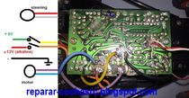
Check the voltages for those colors of the wires.
If you have turned the adjustable potentiometers (trimmers) without knowing what they are for, do this:
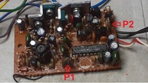
P1 is a voltage reference for the integrated circuit. Check that at pin 3 = 3.7V and now turn P1 until pin 20 = 1.7V.
P2 is the Turbo function activation setting
|
publicité
16-06-2022 à 15h17
| Creation du fichier ..../fichier/pub_log.txt
|
Shunsuke
16-06-2022 à 18h37
|
Thanks Korreka,
i look too for this wiring diagram to the connection of the servo.
I check this voltage on the uP soon as possible.
I hope the servo don't have any fault.
Thanks again,
Shunsuke
Anonyme, 13 msg, (IT). |
Shunsuke
16-06-2022 à 22h06
|
Hi Korreka,
I have on pin 3, 3.6V for reference.
I have adjust p1 for 1.7V but nothing changed,
I adjusted too p2 but nothing changed.
i continue to have no stop position, both motor run together.
Is probably the 2061D faulty?
Thanks so much.
Shunsuke
Anonyme, 13 msg, (IT). |
Korreka
17-06-2022 à 18h47
|
Check this:
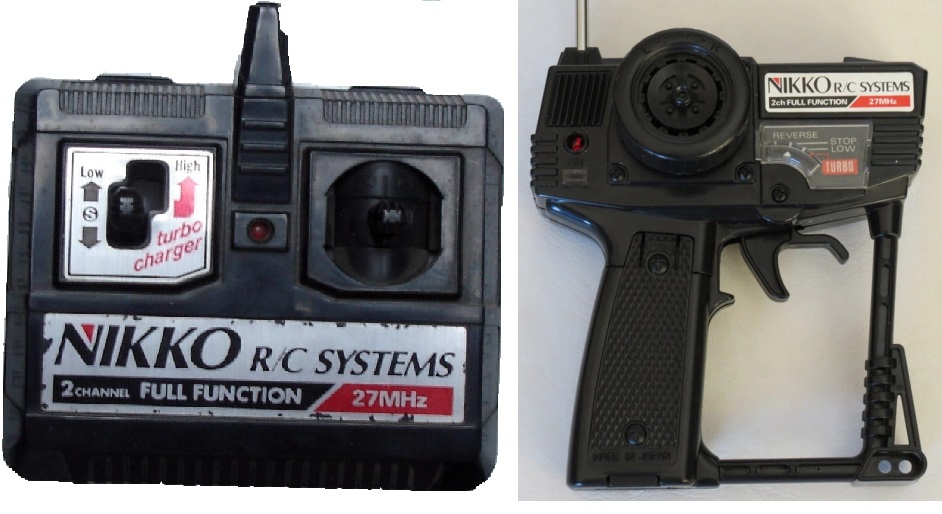
* You are using this transmitter with Turbo:

* This transmitter (2ch Full function) is not compatible
* Check that +12V is orange wire and +6V is yellow wire and not vice versa
* Backward, Forward, Left and Right signals come out of 2016D i.c.
The Turbo signal comes from a filter made up of transistors and capacitors.
You can measure the forward and backward voltages on pins 17 and 18 . The Turbo also activates Forward signal.
This diagram is from Black Fox and will work for Turbo Panther:
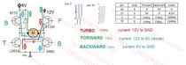
* If you had an oscilloscope, you could see if the Forward (700-800Hz), Backward (300-350Hz) and Turbo (1000-1100Hz) signals on pin 8 are correct.
|
Shunsuke
17-06-2022 à 22h09
|
Thanks so much Korreka.
I have the full function 27.145 MHz. (Not 2 channel).
All voltage are correct you said on the pin 17 and 18, voltage wiring B+ are ok.
I make a test; i remove both motor, and i connect two multimeter, to the servo motor output.
I have aligned the turbo and now surprisly i have the stop position (0V on both meter).
I have full function now with stop. The servo are always working correctly, i think.
It's the motors "sit down" the servo and the uP go out of control.
I need to change the motor?
The motor are two RE-260 mabuchi just for test.
Thanks so much again.
Shunsuke
Anonyme, 13 msg, (IT). |
publicité
17-06-2022 à 22h09
| Creation du fichier ..../fichier/pub_log.txt
|
Charly
18-06-2022 à 10h18
 |
Please upload your picture directly on the forum, Please don't use pictures located on other sites (they will disappear soon) .
Charly, Webmaitre,5280 msg, 63 ans. Cesson Sevigne (FR-35). [mon blog] webmestre et administrateur du forum |
16 messages. 1 2 - Nikko R379 / No.381 receiver wiring diagram. [7195]  Messages récents Messages récents |


